Introduction to ER Models
What is an Entity-Relationship Model?
The Entity-Relationship (ER) model is a high-level conceptual data model that helps database designers plan the structure and relationships of data before implementation. Developed by Peter Chen in 1976, it provides a graphical representation of real-world entities and their relationships.
Note: ER modeling is typically the first step in database design, performed before deciding on specific database technologies or implementation details.
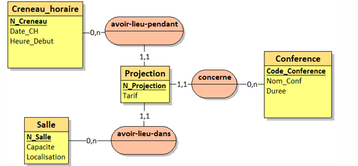
Example of a basic ER diagram showing entities and relationships
Core Components
The ER model consists of three basic concepts:
- Entities: Objects or concepts in the real world that are represented in the database
- Attributes: Properties or characteristics of entities
- Relationships: Associations between entities
Example
In a university database:
- Entities: Student, Course, Professor
- Attributes: Student (ID, Name, Address), Course (Code, Title, Credits)
- Relationships: Student enrolls in Course, Professor teaches Course
Why Use ER Modeling?
ER modeling offers several benefits for database design:
- Provides a clear visual representation of data structures
- Facilitates communication between stakeholders and technical teams
- Helps identify potential issues before implementation
- Creates a blueprint for database implementation
- Makes complex data relationships easier to understand
Quick Check
Which of the following is NOT a basic component of the ER model?
Entities & Attributes
Understanding Entities
An entity is an object or concept that exists in the real world and can be distinctly identified. In database terms, an entity is typically represented as a table when transformed into a relational model.
Types of Entities
- Strong Entity: Can exist independently of other entity types
- Weak Entity: Depends on another entity type for its existence
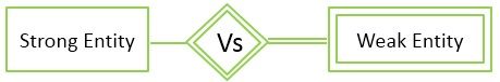
Strong entity (Student) vs Weak entity (Dependent)
Understanding Attributes
Attributes are properties or characteristics that describe an entity. They provide details about an entity and are represented as columns in relational tables.
Types of Attributes
Simple
Cannot be divided further (e.g., StudentID)
Composite
Can be divided into smaller parts (e.g., Address)
Single-valued
Contains only one value (e.g., Birthday)
Multi-valued
Contains multiple values (e.g., PhoneNumbers)
Derived
Value calculated from other attributes (e.g., Age from Birthdate)
Key
Uniquely identifies an entity instance (e.g., StudentID)
Entity and Attribute Example
Consider a Student entity with attributes:
- StudentID (Simple, Key)
- Name (Composite: FirstName, LastName)
- Address (Composite: Street, City, State, ZipCode)
- PhoneNumbers (Multi-valued)
- BirthDate (Simple)
- Age (Derived from BirthDate)
Visual representation of a Student entity with attributes
Practice Exercise
Identify the type of each attribute for the following Product entity:
Relationships
Understanding Relationships
Relationships represent associations between entities. They show how entities interact with each other and are a crucial part of database design. Relationships are typically represented as lines connecting entity boxes in ER diagrams.
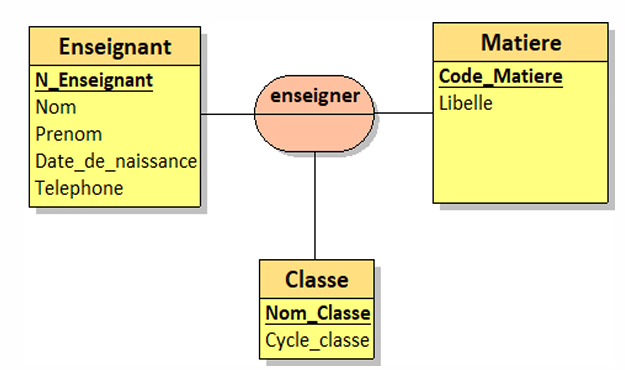
Example of relationships between Class, Course, and Professor entities
Relationship Cardinality
Cardinality defines how many instances of an entity relate to one instance of another entity. There are three main types:
One-to-One (1:1)
1
One instance of Entity A is associated with exactly one instance of Entity B, and vice versa.
Example: Person and Passport (one person has exactly one passport, and one passport belongs to exactly one person)
One-to-Many (1:N)
N
One instance of Entity A is associated with multiple instances of Entity B, but one instance of Entity B is associated with only one instance of Entity A.
Example: Department and Employee (one department has many employees, but each employee belongs to only one department)
Many-to-Many (M:N)
N
One instance of Entity A is associated with multiple instances of Entity B, and one instance of Entity B is associated with multiple instances of Entity A.
Example: Student and Course (one student can enroll in many courses, and one course can have many students)
Relationship Attributes
Sometimes, relationships themselves can have attributes. These attributes describe properties of the relationship rather than the entities involved.
Example: Student Enrolls in Course
Consider a many-to-many relationship between Student and Course entities. The relationship "Enrolls" might have the following attributes:
- EnrollmentDate: When the student enrolled in the course
- Grade: The student's grade in the course
- AttendanceRate: The student's attendance percentage
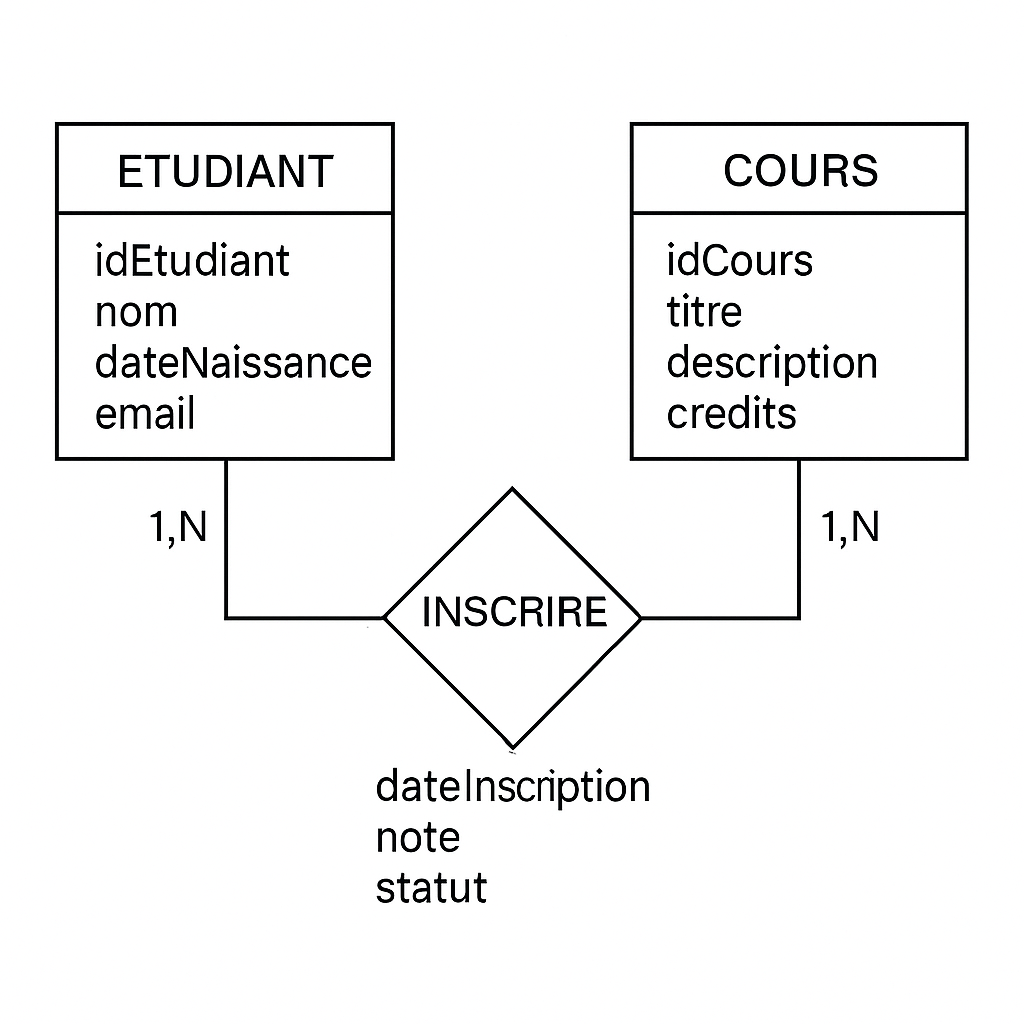
Relationship with attributes between Student and Course entities
Relationship Challenge
Which type of relationship would be most appropriate for Doctor and Patient entities in a hospital system where doctors can have many patients and patients can be treated by multiple doctors?
ER Diagram Challenge
Draw an ER diagram for the following scenario:
A library system needs to track books, authors, and borrowers. Books can have multiple authors, and authors can write multiple books. Borrowers can check out multiple books, but each book can only be checked out by one borrower at a time. The system needs to track when books are checked out and returned.
Advanced ER Concepts
Participation Constraints
Participation constraints specify whether all or only some entity instances participate in a relationship.
Total Participation
Every instance of the entity must participate in the relationship. Represented by a double line in ER diagrams.
Total participation (double line) from Order to Customer
Example: Every Order must be associated with a Customer (an order cannot exist without a customer).
Partial Participation
Some instances of the entity may participate in the relationship, but not all. Represented by a single line in ER diagrams.
Partial participation (single line) from Customer to Order
Example: Not every Customer must have placed an Order (a customer can exist without having placed any orders).
Specialization and Generalization
These concepts help to model hierarchical relationships between entity types.
Specialization
The process of defining subsets of an entity type that have distinctive attributes or relationships.
Specialization: Vehicle → Car, Truck, Motorcycle
Example: Vehicle can be specialized into Car, Truck, and Motorcycle, each with specific attributes.
Generalization
The reverse process of abstraction, where similar entities are generalized into a higher-level entity type.
Generalization: Savings Account, Checking Account → Bank Account
Example: Savings Account and Checking Account can be generalized into Bank Account.
Inheritance
Inheritance in ER modeling allows subclass entities to inherit attributes and relationships from their superclass.
Person entity with Employee and Customer as subclasses
In the example above:
- Person is the superclass with attributes like PersonID, Name, and Address
- Employee is a subclass with additional attributes like EmployeeID, Salary, and Department
- Customer is a subclass with additional attributes like CustomerID, CreditLimit, and CustomerType
- Both Employee and Customer inherit the attributes of Person
Aggregation
Aggregation represents a "part-of" relationship where an entity is made up of component entities but those components can exist independently.
Aggregation: Department consists of Employees
Example: A Department consists of multiple Employees, but Employees can exist independently of the Department.
Advanced Concepts Quiz
Case Study: University Management System
Apply your knowledge of advanced ER concepts to analyze this university system:
Advanced ER model for a university management system
Notice how this diagram incorporates:
- Inheritance (Person → Student, Faculty)
- Aggregation (Department consists of Faculty)
- Total and partial participation constraints
- Complex relationships with attributes
Think About It
How would you modify this diagram to include the concept of Research Projects where faculty members from different departments can collaborate?
Converting ER Models to Relational Schema
Why Convert ER to Relational?
The Entity-Relationship model provides a conceptual design of the database, but most database systems implement the relational model. Converting an ER diagram to a relational schema is a critical step in database implementation.
Note: Relational databases store data in tables with rows and columns, where each table represents an entity or relationship from the ER model.
Basic Mapping Rules
Follow these rules to convert your ER diagram to a relational schema:
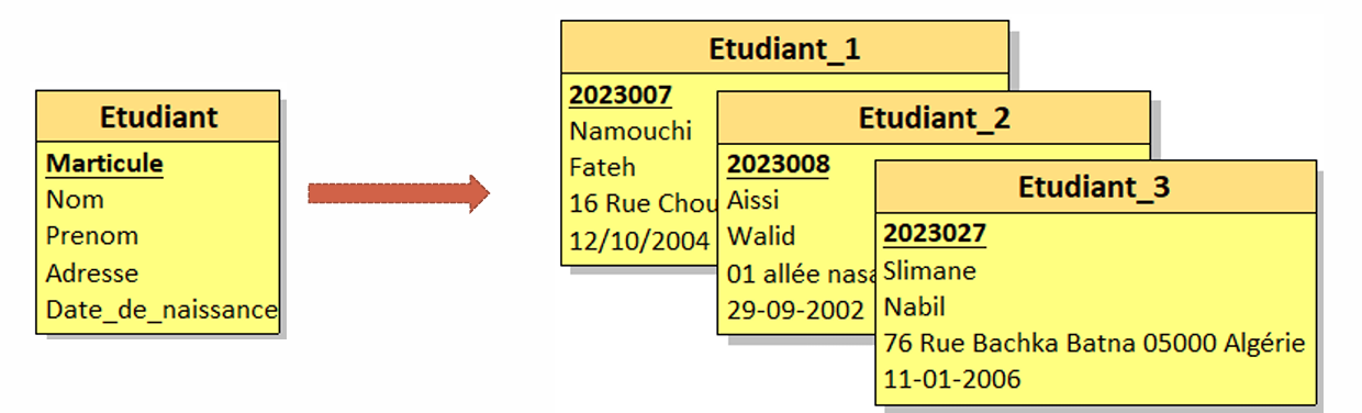
1. Regular Entity Types
Create a relation (table) for each regular entity type.
- The primary key of the entity becomes the primary key of the relation
- All simple attributes become attributes (columns) of the relation
- For composite attributes, include only their simple components
Example: Student entity with attributes (StudentID, Name, Address) becomes:
Student(StudentID, FirstName, LastName, Street, City, State, ZipCode)
2. Weak Entity Types
Create a relation for each weak entity type:
- Include all attributes of the weak entity
- Include the primary key of the identifying (owner) entity as a foreign key
- The primary key is a combination of the owner's primary key and the weak entity's partial key
Example: Dependent weak entity related to Employee becomes:
Dependent(EmployeeID, DependentName, Relationship, BirthDate)
where EmployeeID is a foreign key referencing Employee
3. Binary 1:1 Relationships
Choose one of the related entities and include the primary key of the other as a foreign key:
- Prefer including the foreign key in the entity with total participation
- Include all attributes of the relationship as attributes of the relation
Example: Person and Passport with 1:1 relationship becomes:
Person(PersonID, Name, ...)
Passport(PassportNumber, IssueDate, ExpiryDate, PersonID)
where PersonID in Passport references Person
4. Binary 1:N Relationships
Include the primary key of the entity on the "one" side as a foreign key in the relation for the entity on the "many" side:
- Include all attributes of the relationship in the "many" side relation
Example: Department and Employee with 1:N relationship becomes:
Department(DeptID, DeptName, Location, ...)
Employee(EmployeeID, Name, Salary, DeptID, ...)
where DeptID in Employee references Department
5. Binary M:N Relationships
Create a new relation for the relationship:
- Include the primary keys of both participating entities as foreign keys
- The combination of these foreign keys forms the primary key of the new relation
- Include all attributes of the relationship
Example: Student and Course with M:N relationship "Enrolls" becomes:
Student(StudentID, Name, ...)
Course(CourseID, Title, Credits, ...)
Enrollment(StudentID, CourseID, EnrollmentDate, Grade)
where StudentID and CourseID reference Student and Course respectively
Handling Advanced Concepts
Mapping Specialization/Generalization
There are multiple approaches to mapping inheritance hierarchies:
Single Table Approach
Create one table for the entire hierarchy with all attributes and a discriminator column:
Single table for Person, Employee, and Customer
Person(PersonID, Name, Address, PersonType, EmployeeID, Salary, Department, CustomerID, CreditLimit, CustomerType)
Pros: Simple, good performance for queries across the hierarchy
Cons: Many null values, potential for large tables
Table Per Entity Approach
Create separate tables for the superclass and each subclass with appropriate references:
Separate tables with foreign keys
Person(PersonID, Name, Address)
Employee(EmployeeID, PersonID, Salary, Department)
Customer(CustomerID, PersonID, CreditLimit, CustomerType)
Pros: No null values, normalized structure
Cons: Requires joins for complete entity data
Table Per Subclass Approach
Create a separate table for each subclass with all attributes (including inherited ones):
Separate tables with duplicated attributes
Employee(PersonID, Name, Address, EmployeeID, Salary, Department)
Customer(PersonID, Name, Address, CustomerID, CreditLimit, CustomerType)
Pros: Good query performance for specific subclasses
Cons: Data redundancy, update anomalies
ER to Relational Conversion Exercise
Convert the following ER diagram to a relational schema:
Library system ER diagram from Lesson 3
Final Knowledge Check
Congratulations!
You've completed the Entity Relationship Model course